Advanced Crane Controls Laboratory: 7-ft Scale Apparatus of Luffing Jib Tower Crane
Project Overview
The Advanced Crane Controls Laboratory at Georgia Tech was established following a crane incident in the state of Washington that resulted in numerous fatalities. Now, this laboratory of students across various disciplines is working on a wide variey of projects all sharing the overall goal of improving crane safety practices and preventing future incidients. As a student researcher in Georgia Tech's Advanced Crane Controls Laboratory, I collaborated with a team to design and construct a 7-foot scale model of a luffing jib tower crane. Our goal was to replicate the crane as accurately as possible to conduct a series of repeated tip-over tests. These tests aim to determine key safety parameters, which will help improve real-world crane safety applications. In August of 2025, our paper was presented at the ASME research conference in Anaheim, California. Initially, a 3-foot scale model was constructed and tested to evaluate design practicality.

Before designing the 7-foot model, a 3-foot scale model was constructed to test various catch mechanisms, sensor integrations, tilt angles, acceptable loads, and machine deck configurations. The CAD design for the 3-foot model is shown above. This initial prototype was successful, achieving full 360-degree motion and luffing up to 80 degrees. Several catch mechanisms were tested to evaluate their effectiveness in safely capturing the crane after tip-over at angles up to 20 degrees. Additionally, sensor-integrated catch mechanisms were trialed to assess their functionality. Finally, acceptable load parameters were determined, which informed the design and load specifications for the larger model.

The CAD of this internal catch mechanism integrated a sensor to obtain data on the angles the crane reached prior to tip over.
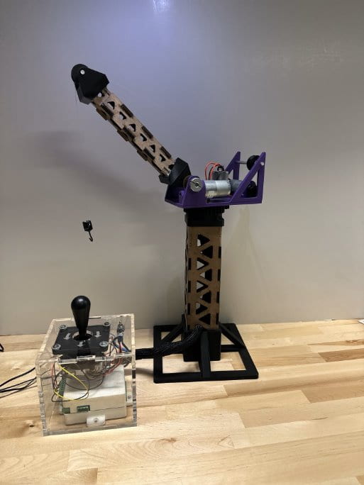
The completed 3-foot crane model is shown above. This model was constructed from MDF and a variety of 3D printed components.
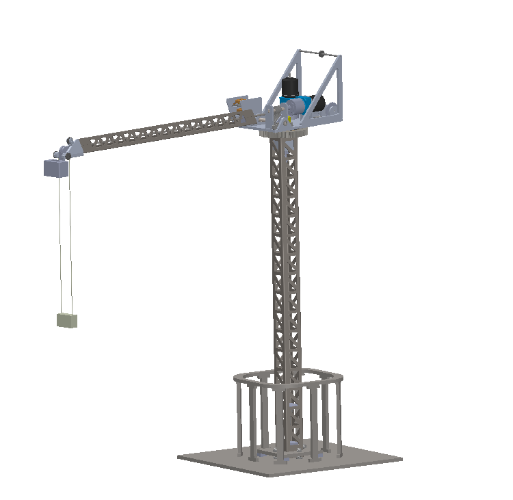
The completed CAD of the 7-foot scale apparatus features the selected external catch mechanism mounted on the base plate. Additionally, this model incorporates a camera angle sensor at the end of the jib to continuously track the position of the load. There is a 4-bar linkage designed to maintain orientation of the camera angle sensor, so it stays positioned directly above the load while the crane luffs.
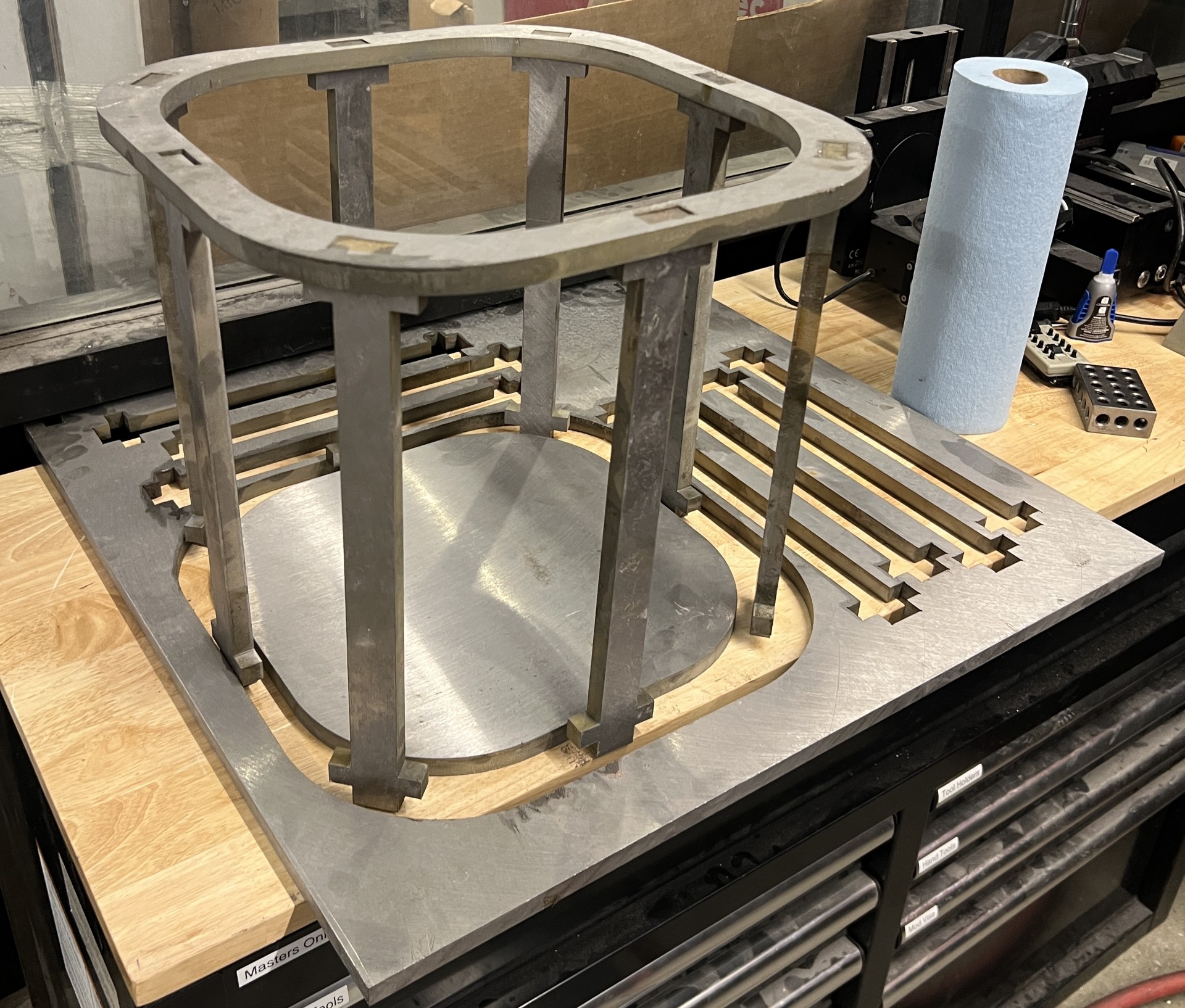
The team machined the majority of components for the final model in-house. Machining methods consisted of using a waterjet to cut out various components, using a metal mill and lathe to create custom pieces, welding components together, and a variety of others. For example, the image above shows the external catch mechanism assembled after the pieces were cut on a waterjet and prior to welding.
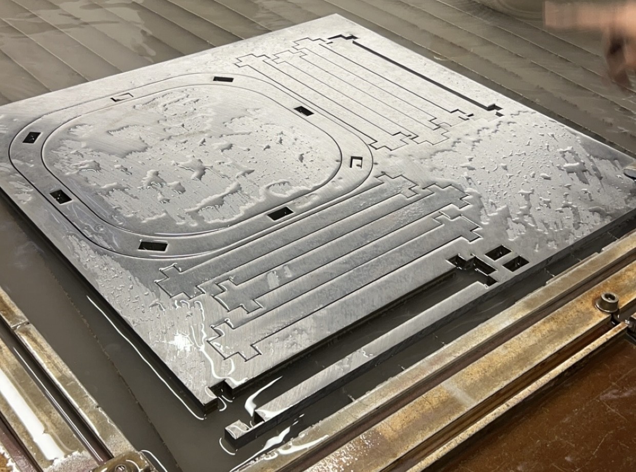
Components for the catch mechanism where cut on the waterjet prior to assembly.
Closeup of camera angle sensor 4-bar linkage mechanism.
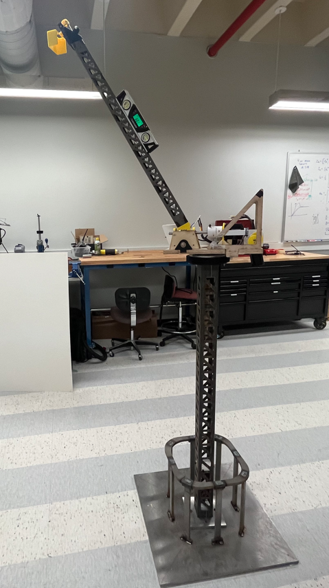
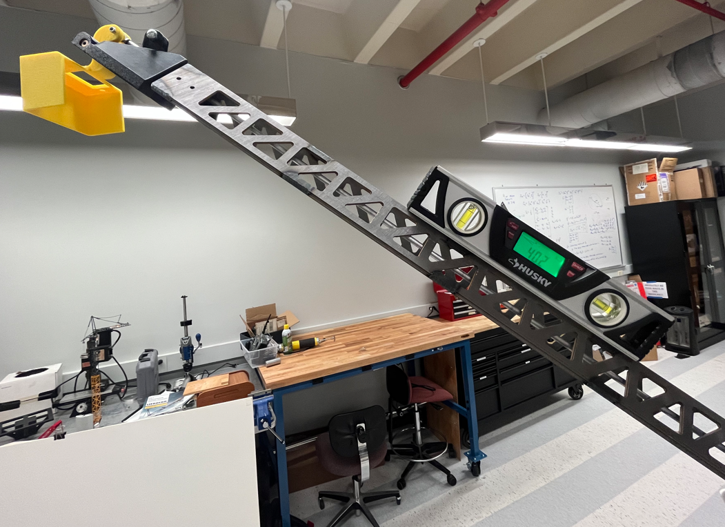
Almost fully constructed 7-ft crane model. A preliminary machine deck of plywood is featured here which was tested and verified prior to machining and implementing the finalized machine deck.
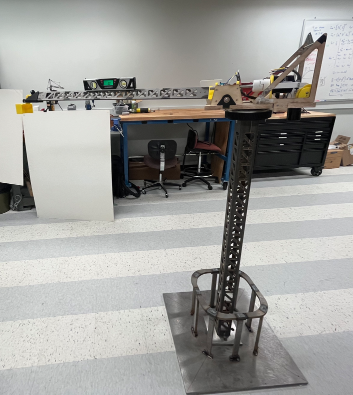
Another angle of the almost full constructed 7-ft model.

Components for the catch mechanism where cut on the waterjet prior to assembly.
Video of hoisting motion.
Video of luffing motion.
Additional Details
Non-pictured Steps
- I have been trained and tested to operate a MAXIEM Waterjet. Steps to properly machining pieces on the Waterjet include converting .stl files to .dxf files and utilizing relevant softwares to successfully prepare files for operation.
- Many more catch mechanisms where designed and tested than what I have shown here.
- Additional responsibilities as a student researcher include attending weekly update meetings and sometimes presenting in those meetings.
- I additionally helped format posters, presentations, and the website for the Advanced Crane Controls Laboratory.
Learning Process
- I learned a significant amount about the importance of designing for machinability.
- Extensive research was conducted to develop a comprehensive Bill of Materials for this project. Numerous critical decisions were made regarding the suitability of components for the crane. This included selecting commonly used components that met the application’s requirements, evaluating manufacturers for custom one-time components, and determining whether to machine parts in-house. Every decision carefully considered factors such as cost, time efficiency, and practicality to ensure the crane met all necessary requirements while staying within budget and adhering to time constraints.
- I gained valuable experience in rapid prototyping, learning how models can effectively represent real-world scenarios, even without achieving perfect accuracy.